


great removers
Reading time:utilisation conditions
degreasing UWW before it is discharged into the sewer
This pre-treatment «at source» is recommended and often compulsory for a number or small-scale businesses (restaurants, local authorities etc.). Standard separators (or grease traps) are mass produced for flow rates ranging from 20 to 30 L · s–1. These units have been designed for a 3 to 5 minutes contact time and a rising velocity of approximately 15 m · h–1.
Properly operated, they can screen out up to approximately 80% of solidified fats and store approximately 40 L of light matter per L·s–1 of infeed flow. Regular cleaning is essential. Water temperature must not exceed 30°C. These units have been designed to prevent, whenever possible, the formation of deposits of heavy matter. However, the upstream inclusion of a tank for settling the bulkier matter can be beneficial, providing a 1 to 3 minutes contact time and being easy to clean.
grease removal used as a pre-treatment in wastewater treatment plant
A primary settling tank is required to separate out the grease that accumulates on the surface; however, it is usually not very suitable for recovering large quantities of this grease, creating operating problems.
With domestic wastewater, grease removal becomes essential when there is no primary sedimentation; this function can be combined with grit removal to great advantage providing that the dimensions of the structure have been calculated accordingly (approximately 15 minutes contact time) and that means are provided for separating out the organic matter that settles with the grit.
For some agrifood industry wastewater containing large quantities of grease that needs to be screened out (especially abattoirs, meat industries), we recommend the inclusion of a separate grease remover, designed for hydraulic loading of 10 to 20 m3·h–1 by m2 of useful surface area. Positioned upstream from the discharge into the sewer, it protects the network or can be useful as an initial treatment stage in a specific IWW plant.
These structures have not been designed to screen out oils and hydrocarbons; where applicable these will be screened out during the primary settling stage.
circular grit-grease remover
These 3 to 8 m diameter cylindrical-conical structures have a 3 to 5 m liquid depth at the centre. They are equipped with an «Aéroflot» type submerged axially positioned aerator-mixer (photo 9).

The mixer-aerator has a centrifugal pumping mobile that is submerged under approximately 2 m of water and driven by a submerged electric motor that develops a specific output of 15 to 30 W per m³ of liquid capacity.
The mobile:
- generates a gyrating flow through the lower parts of the structure, encouraging the grit to slide down the 45° hopper slopes;
- creates a point turbulence zone that encourages grease to separate from the bonded matter;
- takes in a certain flow of ambient air through a free air duct and releases this air into the mass as fine dispersed bubbles. They primarily adhere to hydrophobic grease particles and help the latter to float.
In the structure, the water is introduced at a tangent into a central submerged cylindrical baffle that surrounds the submerged aerator. The water is then recovered through a submerged opening in the cylindrical wall.
Grit is collected as described under the section structures.
Grease that is floated to the surface is continuously collected by a slow speed skimming unit; the skimmed grease is drained and then pushed onto the slope of an above-water weir before falling into the collection trough. The grease is usually gravity discharged into a storage skip or to a lift pump (air pump) before being routed to a specific grease treatment stage (see the biomaster principle).
rectangular grit-grease remover
Having exactly the same size as the rectangular grit remover described under the section structures, this unit is used to process major throughputs of up to 5,000 m3·h–1 (photo 10 and figure 11).
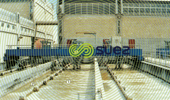
This system has the following treatment stages:
- zone 1: aerated zone where the grease is synthesised;
- zone 2: calm zone where grease is concentrated and recovered by skimming;
- zone 3: combined scraper bridge for grease skimming and pumped grit extraction.
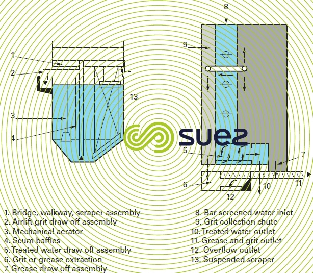
The structure’s cross section has a configuration that is appropriate to the flow of cross-sweeping streams, with slopes that encourage the grit to collect on the floor of the structure (spiral flow). Water is fed into the structure’s inlet and collected at the opposite end, through a submerged opening passing, quite often, over a downstream weir designed to maintain the water sheet level.
The structure, with its slow longitudinal flow, normally has two linked mixing and aeration systems that create gyrating cross flows that are independent of water flow rate and that, consequently, tolerate major longitudinal transit velocity fluctuations. This velocity can be quite slow without creating any problems:
- if necessary, a pre-grit removal infeed area (that can be up to one third of the structure’s length) having an in-line air injection system equipped with appropriate air diffusers such as the Vibrair, delivering a specific aeration output of approximately 20 to 30 W · m–3. The injected air maintains a cross circulation velocity and its turbulent effect encourages organic matter to become detached from the grit particles; this air also prevents massive accumulations of large size grit at the plant inlet (identical to the grit remover covered under the section structures);
- the remainder of the structure, devoted to grease removal and to fine grit removal, has a series of submerged aerators arranged in line, creating a slower gyrating motion and floating the grease.
Grit is extracted using the same devices - skimming, pumping or emulsifier mounted on the mobile bridge ... - as those described under the section structures.
The moving bridge skims the grease that floats on the surface and routes it towards the end of the structure, where is extracted according to a programmed sequence:
- either by being pushed onto an above-water weir slope; the grease is immediately collected in a pit, mobile skip or pumped out;
- or removed by a weir penstock (powered and programmed): via hydraulic transport to an adjacent separation unit (see specific grease treatment).
rectangular grease remover with aerators-mixers at the inlet
A variant of the above unit will sometimes be justified (in the case of water containing small amounts of large grit) with only one or two aerators-mixers installed on the inlet. These units have a vertical axis submerged screw. An appropriate diffuser is used to inject an adjustable pressurized air flow beneath this screw. This aerator-mixer has been designed for use with large units and performs the same functions as the submerged aerator with the possibility of separate mixing and aeration adjustment.
grease removal performances
«Grease» includes three forms of carbonaceous compounds: fatty acids, simple and complex lipids. Various extraction methods have been used to quantify the grease content of wastewater; the most specific appears to be extraction using hexane (MEH) and methanol. The daily UWW fats output is 15 to 20 g of fats per p.e. (expressed as MEH [f.p.e.]). Fats have a density of approximately 0.9. Grease remover efficiency varies from 5 to 15% of total MEH and, expressed as MEH, the total concentration of grease recovered after floatation is between 13 and 100 g · L–1 and as DOC, between 40 and 300 g · L–1.
The low efficiency of grease removers compared with the MEH may surprise but we need to remember that:
- grease only represents as small fraction of the total MEH since only the solidified MEH comes together as fairly large aggregates (> 50 μ) that can be collected, without the use of reagents, by the bubbles of this coarse flotation system;
- additionally, other oils, in the form of fine emulsions, or in a soluble form, will not have any effect on the biological aspect. In fact, at the aerator, only those greases described in the foregoing will tend to float and form «scum» that accumulates on the surface and could act as «nests» for threadlike species such as the Nocardia.
Bookmark tool
Click on the bookmark tool, highlight the last read paragraph to continue your reading later
